Edge Trimmer
The edge trimmer is indispensable core equipment deployed on continuous strip processing lines for metallurgical plants. After hot‑rolling and cold‑rolling operations, strip steel frequently generates micro‑cracks, burrs and irregular contour defects along both side edges. Without targeted trimming, these edge flaws will expand under tension in subsequent processes such as leveling, annealing and galvanizing, finally causing unexpected strip breakage, unplanned line shutdown and massive production loss.
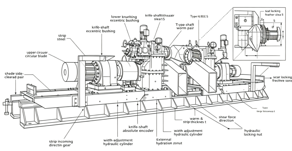
The equipment in the picture adopts double‑head cantilever rotary hybrid‑power shearing architecture. Two sets of vertically installed, horizontally displaceable circular blades perform strip shearing by precisely setting blade side clearance and overlap value. When strip steel passes through the shear point, shear stress acts on the contact zone between blades and strip. Contact area yields plastic deformation; as blade penetration depth rises, material deformation accumulates continuously. Once deformation exceeds the fracture limit of strip material, the edge portion fractures and separates, completing high‑quality edge trimming.
- Working Principleof Edge Trimmer
Precisely set side clearance (horizontal gap) and overlap (vertical engagement depth) between circular blades according to strip thickness, tensile strength. Strip steel is fed at line speed into the shear zone. Local plastic deformation occurs under shear force. Material fractures when deformation reaches fracture threshold, scrap edges are separated from qualified strip. Accurate adjustment of overlap & side clearance is decisive for trimming quality: improper parameters will produce burrs, tearing edge or over‑loading of blade assemblies.
- Core Structural & Technical Features
2.1 Double‑head cantilever rotary hybrid‑power shear structure
Cantilever layout facilitates blade replacement, inspection and daily maintenance without disassembling large‑scale frame components. Hybrid‑power configuration delivers stable shear torque for high‑strength carbon steel, silicon steel and alloy strip.
Double‑edged circular blade, end‑face grinding, hydraulic nut locking
Blades adopt double‑sided usable design to extend service life. End‑face grinding guarantees flatness of shear face. Hydraulic nut locking eliminates blade loosening under cyclic shear impact, ensuring long‑term shearing stability.
2.2 Opening width adjustment system
Two hydraulic cylinders drive transverse displacement for shear‑width adjustment. Servo cylinders realize high‑precision width positioning; the physical stroke of hydraulic cylinders defines the full adjustable opening range, adapting for multiple strip width specifications.
2.3Shear blade overlap adjustment
Worm‑geared motor fitted with external absolute encoder drives worm‑gear transmission, rotating the knife‑shaft eccentric bushing. Eccentric rotation changes vertical relative position of upper and lower blades, realizing precise overlap setting. Closed‑loop encoder feedback avoids manual calibration errors.
2.4Shear blade side‑clearance adjustment
Driven by another worm‑geared motor with external absolute encoder. Worm component and knife‑shaft sleeve adopt trapezoidal (T‑type) thread connection. Worm‑gear assembly drives axial movement of knife‑shaft sleeve to tune horizontal side clearance between upper‑lower blades. Side‑clearance parameters can be matched according to strip thickness and material grade.
3.Main Functions
Trim defective edges of incoming strip steel;
Maintain consistent finished strip width within tolerance;
Remove edge micro‑cracks and inhibit crack propagation in downstream working sections;
Eliminate edge burrs to improve surface quality of finished strip.
4.Typical Application Scenarios
- continuous pickling lines
- continuous annealing lines
- galvanizing lines
- temper‑tension leveling lines for carbon steel, alloy strip, silicon steel in metallurgical plants.
- Topics You may Be Interested In:
- Side trimmer
- Scrap chopper
- Multi-roll Leveler
- Work Roll
- Back up roll